Lecture 19: Function-Oriented Design
Relationship to Textbook
- This lecture is partially based on material in Chapter 6 of the Jalote textbook
Software Design
- Software design is a many splendored thing… it is a fun creative activity with many different aspects
- In this class, we will look at traditional notions of design, courtesy of our Jalote textbook
- but we will also spend a lecture looking at other aspects of design: design patterns, design by convention, etc.
- We first look at the design phase in general and then examine function-oriented design as manifested by structure charts and the structured design approach
Software Design, continued
- In software design, we create a solution (or solutions) to the problems identified by the software requirements phase
- What approach should we take to solve the problem we are confronting?
- Consider Hex Fiend, a hex editor for MacOS X
- This is a program designed to open and edit files that are multi-gigabytes in size!
- In order to create a program like this, you can't, for instance, rely on techniques that attempt to read the contents of a file into memory!
- The algorithms and data structures used by a program like this are very different from applications that deal with much smaller file sizes
- Note: this program is free and open source. If you're curious how a program like this works, download it and give it a look!
- Design typically consists of a “high-level” phase and a “low-level” phase
- High-level design focuses on the modules that make up a system and their relationships
- Indeed, Jalote equates high-level design with the “module view” of software architecture that we discussed in the previous lecture
- Low-level design focuses on the details of each module identified during high-level design
- While we present these phases in sequence during lecture, during the creation of a software system you will iterate between the two phases, sometimes very quickly
- Function-oriented design views a system as a set of modules with clearly defined behavior that interact with each other in a clearly defined manner to meet the system's requirements.
Design Methodologies
- There are many different ways to create a design: design methodologies aim to reduce the search space
- A design methodology is a systematic approach to creating a design by applying a particular set of techniques and following a particular set of guidelines
- These methodologies…
- provide a disciplined approach to dealing with complexity
- deal primarily with high-level design issues as opposed to low-level design issues
- often are suited for a particular application domain
- The rules and techniques of a design methodology are often “loose”: they do not attempt to reduce design to a sequence of mechanical steps
- After all, design is primarily a creative activity
- There will not be a single correct solution to a given set of requirements
Design Objectives
- The goal of software design is to find the best possible design that meets your needs
- You may have to explore different designs
- Unfortunately, evaluation criteria for a design are often subjective and non-quantifiable
- Major criteria to evaluate a design
- Correctness
- A software design is correct if a system built precisely according to the design satisfies the requirements of the system
- A design should be verifiable (does an implementation match the design), complete (does the design address its specified requirements) and traceable (all design elements can be traced back to specific requirements)
- Efficiency
- Does the design efficiently make use of scarce resources: such as memory on a wireless sensor
- Maintainability
- How easy is it for the design of a system to be understood?
- Simpler designs make it easy for a developer to understand and then maintain the system
- Cost
- Does the design help to reduce costs in later phases of software development?
- Can one design achieve the same quality as another design while reducing costs?
Design Principles
- Problem Partitioning and Hierarchy
- Abstraction
- Modularity
Problem Partitioning and Hierarchy
Divide and Conquer
- Decompose system into smaller and smaller pieces
- Ideally, each piece can be solved separately
- Ideally, each piece can be modified independent of other pieces
- Reality: each piece must communicate with other pieces
- This communication implies a certain cost
- At some point the cost is more than the benefit provided by the individual pieces
- At this point, the decomposition process can stop
Abstraction
- Abstraction is a powerful concept used in all engineering disciplines
- It is a tool that permits a developer to consider a component in terms of the services it provides without worrying about the details of its implementation
- We can say
This component calculates payment schedules for a wide range of loans. We provide the loan amount, interest rate, downpayment, etc. and it returns a payment schedule.
- And during high-level design, that is sufficient. We don't have to worry about the exact set of parameters or the exact format for the payment schedule.
- Indeed, we can treat “payment schedule” as a type and go on to say
After we get a payment schedule, we can send it to the WebFormatter component to produce an HTML fragment that can display the schedule. We'll send the fragment to our WebTemplate component to produce an entire HTML document that we can return to the client.
- Abstraction is an excellent tool for creating a hierarchical understanding of a system's functionality
- We talk about “viewing a system at one level of abstraction” or about “drilling down” to a lower level of abstraction
- We've seen this with data flow diagrams that can start out as context diagrams and then be decomposed into diagrams at lower and lower levels of abstraction
- Eventually, you will reach a level of abstraction where the services talked about at the level above can be implemented with the services of a program language (which is yet another layer of abstraction)
- In design contexts, you might see references to two “types” of abstraction
- functional abstraction: a module is specified by the functions it performms
- data abstraction: a data structure is manipulated in terms of pre-defined operations; the implementation of the data structure is hidden from its users
- The former is primarily used in functional design, the latter is used primarily in object-oriented design
- I say “primarily” because both can be used in either approach to design
Modularity
- A system is considered modular if it consists of discreet components so that each component can be implemented separately, and a change to one component has minimal impact on other components
- Each component needs to support a well-defined abstraction and have a specific interface that other modules use to interact with it
- As Jalote says
Modularity is where abstraction and partitioning come together.
Top-Down vs Bottom-Up Design
- A system consists of a set of components, which have (sub)components of their own
- The highest level component is the system itself, a concept we have seen when discussing context diagrams
- The lowest level components are highly cohesive, loosely coupled implementation units written in some form of programming language
- We can design such a hierarchy using either a top-down approach or a bottom-up approach
- In reality, we use both approaches and
meet in the middle
- A top-down approach starts with the system as a whole, and using stepwise refinement, decomposes it into sub-components that exist at lower levels of abstraction
- A bottom-up approach starts with primitive components that provide foundational services and using layers of abstraction builds the functionality the system needs until the entire system has been realized
- A top-down approach is typically more useful in situations in which an application is being built from scratch
- A bottom-up approach is thus more useful in situations in which a new application is being created from an existing (legacy) system
Module-Level Concepts
- Jalote includes a discussion of cohesion and coupling at this point in chapter 6
- As I discussed these concepts back in lecture 10, I will skip them here
Design Notation and Specification
- During design, there needs to be a way in which design decisions are captured
- Natural language text can be used to capture some of these decisions, or for capturing the rationale for a certain set of decisions
- For instance, the author of Hex Fiend can say
The rationale for keeping only a small amount of a file in memory at any one time is to allow my program to scale to handle multi-gigabyte files.
- However, natural language often does a poor job of capturing decisions made with respect to a system's structure: as a result, graphical design notations have been developed
- Most of these notations are simply variations of the old standby: boxes and arrows
- For object-oriented design, UML is the primary design notation. For function-oriented design, a variety of notations exist. We will look at one notation called structure charts which is used with a design methodology known as structured design
State Charts
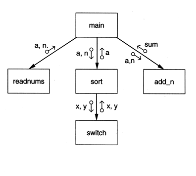
- A structure chart is a graphical representation of a system's structure; in particular, its modules and their interconnections
- Reminder: this is different from object-oriented design: here each module has a well defined function and we are showing how functions work together to achieve a particular objective
- Each module is represented by a box
- If A uses B, then an arrow is drawn from A to B
- B is called the subordinate of A
- A is called the superordinate of B
- An arrow is labeled with the parameters received by B as input and the parameters returned by B as output
- Arrows indicate the direction in which parameters flow
- Parameters can be data (shown as unfilled circles at the tail of a label) or control information (filled circles at the tail)
State Chart Example
Supporting Iteration and Branching
- Structure charts can also support the specification of module relationships that involve iteration and/or branching
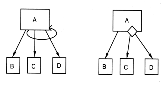
On the left, A invokes modules C and D in a loop. On the right, A will call either C or D based on some sort of decision. Note: the presence of a decision is indicated by the diamond, but details of the decision (at least above) are documented elsewhere.
Types of Modules
- Input: A module that only produces information that is passed to its superordinate
- Output: A module that only receives information from its superordinate for output to a device
- Transform: A module that converts data from one format into another format, possibly generating entirely new information. For example, a module that converts a JPEG image to a PNG image is a transform, but a module that takes a set of numbers and computes their mean is also a transform
- Coordinator: A module that manages the flow of data to and from different subordinates
- Composite: Modules that combine one or more of the above styles are composite modules
Design specification
- In addition to capturing the structure of a system with a design notation, a designer must also create a textual specification for each module that appears in the system's structure
- A design specification will include
- the system structure captured by a design notation
- For each module, a specification of its
- interface (input and output data types)
- abstract behavior (what the module does)
- a list of the modules used by this module (this information is also captured by the design notation)
- design rationale for each design decision made while creating the above items (its also useful to list decisions that were considered and then rejected along with the reasons why)
Structured Design
- The structured design methodology (SDM) views a system as a transformation function that transforms specified inputs into specified outputs
- The central problem of design, then, is to properly design this function
- Due to this view, SDM is primarily function-oriented and relies heavily on functional abstraction and functional decomposition
- SDM aims to control and influence the structure of the final program. In particular, we attempt to design:
- a hierarchical set of loosely-coupled, functionally-cohesive modules
Factoring
- A key concept of SDM is factoring
- Factoring is the process of decomposing a module so that the bulk of its work is done by its subordinates
- A system is said to be completely factored if all the actual processing is accomplished by bottom-level atomic modules with non-atomic modules largely performing jobs of control and coordination
- SDM attempts to achieve a structure that is close to being completely factored
SDM Strategy
- The overall strategy of SDM is to identify the input and output streams of the system and the primary transformations that have to be performed to produce the output
- High-level modules are then created to perform these major activities, which are later refined (factored)
- There are four major steps in applying this strategy
- Restate the problem as a data flow diagram
- Identify the input and output data elements
- Perform first-level factoring
- Perform additional factoring on input, output and transform branches created in the previous step
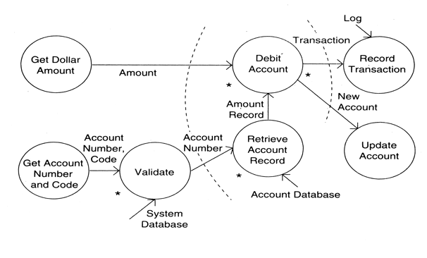
Step 1: Restate the problem as a data flow diagram
- Data flow diagrams during design are focused on the solution domain
- What are the inputs and outputs of our system (as opposed to the inputs and outputs of the problem domain)?
- What are the central transformations?
- Example 1: DFD for an ATM
- Example 2: DFD for a word-counting program
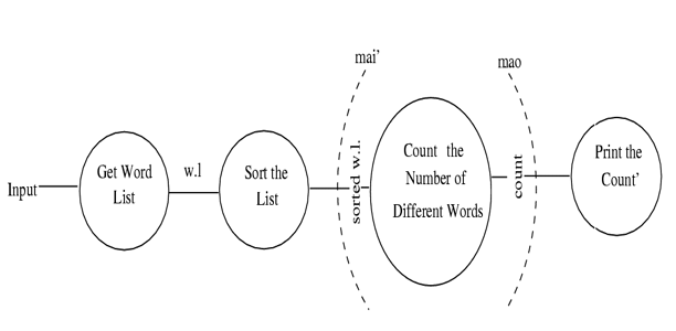
Step 2: Identify the input and output data elements
- What we are looking for is the most abstract input elements (MAI) and the most abstract output elements (MAO)
- The MAI elements are found by going as far as possible from physical inputs without losing the incoming nature of the data element
- The MAO elements are found by identifying the data elements most removed from the physical outputs without losing the outgoing nature of the data element
- For instance, if a system computes element A but outputs element B and the only difference between A and B relates to formatting (for instance converting a list of elements into an HTML table for display), then the MAO element is A, not B.
- Example 1: DFD for an ATM
- Example 2: DFD for a word-counting program
Step 3: First-Level Factoring
- First-level factoring is the first step towards converting the DFD into a structure chart
- You start by creating a module that represents the software system (aka the main module)
- The main module acts as a coordinator module
- For each MAI data element, specify a subordinate input module that delivers these items to the main module
- For each MAO data element, specify an output module
- For each central transform, specify a subordinate transform module
- The inputs and outputs of these transform modules are specified in the DFD
- Example 1: First-Level Factoring of ATM example
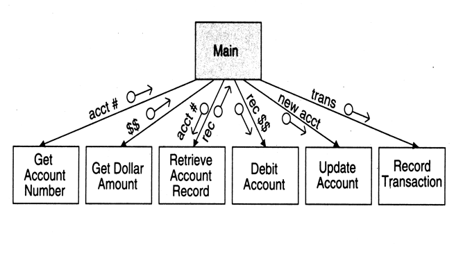
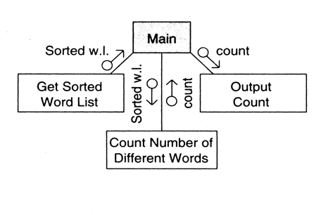
- Example 2: First-Level Factoring of word-counting example
Step 4: Perform Additional Factoring
- Now stepwise refinement is used to specify the sub-modules required to realize the functionality of the modules created in the previous step
- For each input module:
- assume that it is in the main module
- add input modules that takes its MAI data element closer to the raw input
- add transform modules in order to transform the raw input into the desired MAI data element
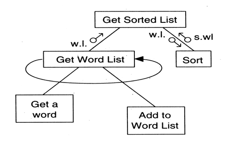
- Example: additional factoring of the word count program
- Output modules are treated in a similar fashion, this time working from MAO data elements to the raw output of the system
- Central transforms are also factored in a stepwise manner until you have specified atomic modules that can be implemented directly
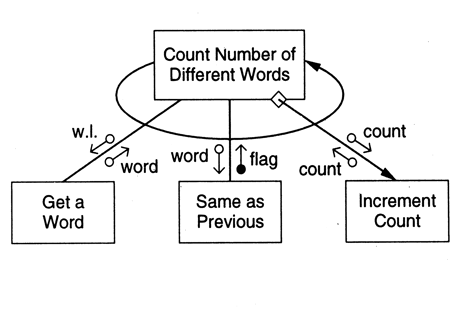
- Example: additional factoring of the word count program
SDM Wrap-Up
- Each new module produced in step 4 can then be examined to see if additional factoring is necessary
- Once the system has been completely factored, a designer will switch to creating the rest of the design specification discussed above
- You are then ready to move on to low-level design, which we will discuss in lecture 21
Verification
- Designs should be checked for internal consistency and for completeness with respect to the SRS
- If a formal design notation is used, then tools may be able to perform some of these checks
- Otherwise, design reviews (as part of your inspection process) are required to ensure that the finished design is of high quailty
- Jalote discusses the composition of a design review team and provides a checklist for the types of questions that should be asked during such a review
Metrics
- Size: Number of Modules x Average LOC expected per module
- Or you can generate LOC estimates for each individual module
- Complexity
- Network Metrics
- Stability Metrics
- Information Flow Metrics
Network Metrics
- Network metrics focus on the structure chart of a system
- They attempt to define how “good” the structure or network is in an effort to quantify the complexity of the call graph
- The simplest structure occurs if the call graph is a tree, with each node having two children
- As a result, the graph impurity metric is defined as nodes - edges - 1
- In the case of a tree, this metric produces the result zero since there is always one more node in a tree than edges
- This metric is designed to make you examine nodes that have high coupling and see if there are ways to reduce this coupling
Stability Metrics
- Stability of a design is a metric that tries to quantify the resistance of a design to the potential ripple effects that are caused by changes in modules
- The creators of this metric argue that the higher the stability of a design, the easier it is to maintain the resulting system
- See Jalote for the details of computing this metric
- The basic idea is to define stability in terms of the number of assumptions made by other components about a particular component.
- This provides a stability value for each particular module
- A formula is then given to combine the stability value of each module into a value for the entire system
- In essense, the lower the amount of coupling between modules, the higher the stability of the overall system
Information Flow Metrics
- Information flow metrics attempt to define the complexity of a system in terms of the total amount of information flowing through its modules
- Jalote discusses two information flow metrics and how they can be used to classify modules
- Approach 1
- A module's complexity depends on its intramodule complexity and its intermodule complexity
- intramodule complexity is approximated by the (estimated) size of the module in lines of code
- intermodule complexity is determined by the total amount of information (abstract data elements) flowing into a module (inflow) and the total amount of information flowing out of a module (outflow)
- The module design complexity Dc is defined as Dc = size * (inflow*outflow)2
- The term (inflow * outflow)2 refers to the total number of input and output combinations, and this number is squared since the interconnections between modules are considered more important to determining the complexity of a module than its code size
- Approach 2
- Approach 1 depends largely on the amount of information flowing in and out of the module
- Approach 2 is a variant that also considers the number of modules connected to a particular module; in addition, the code size of a module is considered insignificant with respect to a module's complexity
- The module design complexity Dc is defined as Dc = (fan_in * fan_out) + (inflow*outflow)
- fan_in above refers to the number of modules that call this module, fan_out is the number of modules called by this module
- Classification
- Neither of these metrics is any good, unless they can tell us when to consider a module “too complex”
- To this end, an approach was developed to compare a module's complexity against the complexity of the other modules in its system
- avg_complexity is defined as the average complexity of the modules in the current design
- std_deviation is defined as the standard deviation in the design complexity of the modules in the current design
- A module can be classified as error prone, complex, or normal using the following conditions
- Dc is the complexity of a particular module
- A module is error prone if Dc > avg_complexity + std_deviation
- A module is complex if avg_complexity < Dc < avg_complexity + std_deviation
- Otherwise a module is considered normal
Coming Up Next
- Lecture 20: Object-Oriented Design
- Lecture 21: Low-Level Design


