Lecture 09: Software Requirements, Part 1
Relationship to Textbook
- This lecture is partially based on material in Chapter 3 of the Jalote textbook
Software Requirements
- Software requirements is the most critical task in software development because it has as its goal understanding the problem that needs to be solved
- If you don't understand the problem, you can't solve it!
- Example
- There is a farmer with a fox, a rabbit, and a prize cabbage. There is a rowing boat, complete with oars, moored on one side of a river. On the other side of the river is a market. There is room in the boat for any two of the four: farmer, fox, rabbit, and cabbage. The fox is hungry, and so is the rabbit. Foxes like to eat rabbits and rabbits like to eat cabbages.
- What's the Problem?
Problem Context versus the Problem to be Solved
- In software development, there is typically one problem context but there may be more than one problem that could be solved
- During the software requirements phase, you need to:
- Understand the problem context
- Determine which problem (or problems) within the problem context need to be solved
- Document your understanding of the problem by creating a software requirements specification (SRS)
- The problem context is also referred to as the application domain.
Software Requirements Specification (SRS)
- The SRS forms the basis of an agreement between a client organization and a development organization
- It needs to be written such that it can be understood by the client while still providing useful information to developers
- SRS also provides information used to validate the final software system; the SRS is used to determine if the final system meets the needs of the client
How does Design factor in?
- After you understand the problem, you will come up with a solution to the problem
- In software development, we solve problems by creating a software system (aka machine) that interacts with elements of the problem domain
- Thus, the software development problem context can be represented as
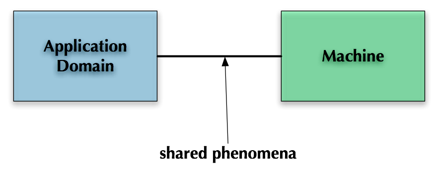
Shared Phenomena?
- There will be some aspects of the application domain that will not be modeled, tracked, or otherwise handled by the machine
- For instance, when controlling elevators, a software system may not care about the movement of cars between floors or the number of passengers in a car
- But there will be other elements of the application domain that are critical to the machine and will thus be tracked
- Elevator Domain: button presses, door open, door close, number of cars, number of floors, etc.
- Similarly, there will be elements of the machine (aka solution domain) that will have no correspondence to elements in the application domain
- The algorithm to schedule the movement of elevators is intangible and will only exist as code stored on a computer; it has no physical counterpart in the elevator domain
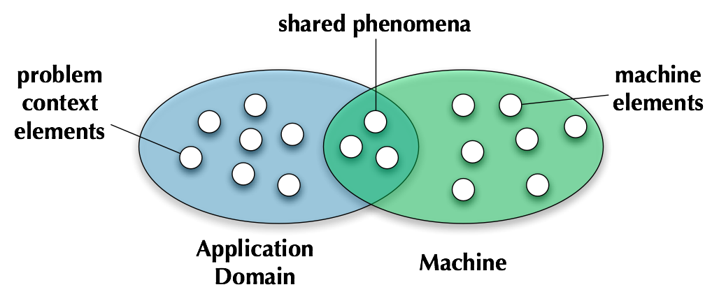
- Those application domain elements that are modeled by the machine are shared and developers must perform work to enable that sharing
- Elevator Domain: A call button must be wired to a hardware device connected to the software system such that pressing the button delivers a signal to the software system. Likewise, if the system determines that car A should go to floor B, there needs to be a mechanism that allows the software to send that command and have it be followed
Software Development Problem Context (Take 2)
- We can thus refine our view of the problem context to create this more detailed picture
Requirements Engineering
- We must understand the application domain and then understand the problem that needs to be solved
- As our understanding grows, we document our understanding via requirements
- What's a requirement?
- IEEE definition
- A condition or capacity needed by a user to solve a problem or achieve an objective
- A condition or capability that must be met or possessed by a system or system component to satisfy a contract, standard, specification or other formally imposed documents
- A documented representation of a condition or capability as in 1 or 2
- (One) Definition of Requirements Engineering
The systematic process of developing requirements through an iterative cooperative process of analyzing the problem, documenting the resulting observations in a variety of representation formats, and checking the accuracy of the understanding gained.
K. Pohl, 1993
Two Phases of Requirements Engineering
- Requirements Elicitation
- The process whereby a development agency discovers what is needed and why (i.e. develops an understanding of the problem and the problem domain)
- Uses knowledge elicitation techniques
- ethnomethodology, human factors, ergonomics, etc.
- Requirements Analysis
- The process of understanding the requirements
- Asks questions about completeness and consistency
- Uses formal methods of systems analysis
- Jalote calls the former problem analysis and the latter product description
The Difficulties of Requirements Engineering
- It is important to understand that performing requirements engineering (RE) is HARD
- Problems
- Developers are not domain experts
- need to learn jargon just to have conversations with domain experts
- will have problems conveying solution-domain concepts to domain experts
- will never fully understand the domain
- must be careful not to alienate domain experts, who may be technology-phobic
- domain experts and end-users (sometimes the two are different groups) may not understand how software will change their environment
- domain experts will not reveal all relevant domain information at once, will be surprised at how much they have to explain to bring developers up to speed
- customer may not know what they want from a system, or may have ideas that are just plain wrong or infeasible
- customer may change their minds about information provided previously
- …
- It is also difficult to transition between the two phases of RE
- It may not be clear how to transform your understanding of the domain into specific requirements
- What formalisms should be used?
- Is natural language enough?
- At some point, you need to be able to specify what the inputs of the system will be and what outputs it should produce WITHOUT specifying a solution to the problem
- In order to make progress, iteration is essential!
- iCronus Example: Prof. Anderson will share some of his experience with the difficulties of requirements analysis based on one of his current research projects
Abstract vs. Detailed Requirements
- Jalote talks about abstract and detailed requirements that further clarifies the difficulty of transitioning between the two phases of RE
- Inventory Control System for a Car Manufacturer
- Abstract Requirements: Stated in terms of the number of parts it has to track, the level of concurrency it has to support, its proposed mode of operation (batch or on-line), what types of information and reports it can generate
- This type of requirement can be useful in determining feasibility, cost, schedule, etc. but its not yet in a state that can be used to create a design and/or implementation
- Detailed Requirements: exact format of the reports, types of queries, types of users, maintenance requirements, archive requirements, data entry formats, etc.
- We must take abstract requirements and augment them with more specific information to get to the point that they are useful in generating a design
Problem Analysis (1 of 2)
- Analysis involves
- interviewing client and users
- reading manuals
- studying current systems
- helping client/users understand new possibilities
- Our goal is to gain an understanding of the needs, requirements, and constraints on the software by understanding the client organization and the system's users
- Issues
- Obtaining the necessary information
- Brainstorming: interacting with clients to establish desired properties
- Information organization, as large amount of info. gets collected
- Ensuring completeness
- Ensuring consistency
- Avoiding early design
- Good communication skills are essential!
Problem Analysis (2 of 2)
- The basic principle used in problem analysis is the same as in any complex task: divide and conquer
- Partition the problem into subproblems
- analyze the sub-problems and understand their relationships
- decompose any sub-problem that is too complex to be solved outright
- The concepts of state and projection can sometimes be used effectively in the partitioning process
- State: Think about the system in terms of its high-level states. Will the system have clearly distinguished modes? Treat each state as a sub-problem
- Projection: Think about the system from the standpoint of different stakeholders. How will users view the system? How will administrators view the system? How will external systems and/or users view the systesm? Treat each perspective as a different sub-problem.
- Methods
- Informal Approach
- Data Flow Modeling
- Object-Oriented Modeling
- Prototyping
Informal Approach
- No defined methodology; info obtained through observation of and interaction with the client organization
- No formal model of the system is created
- Analysis information is organized in the SRS; which is then reviewed with the clients
- Relies on analyst experience and feedback from clients in reviews
- Useful in many contexts since it is easy to implement and very flexible
- even organizations that make use of more formal analysis techniques, may start out with an informal approach before switching to the use of a formalism
Data Flow Modeling
- Data flow modeling (aka structured analysis) is an analysis technique that understands a problem domain by
- identifying input data
- identifying output data
- identifying the functions (aka processes) that convert input data to output data
- This is sometimes called function-based decomposition
- The system is modeled as a series of functions that iteratively transform input data into output data
- This style of analysis tends to lead to system designs in which a system has a small number of data structures that can be manipulated by many different functions
- It makes use of two modeling techniques: data flow diagrams and data dictionaries
Data Flow Diagrams
- Shows the flow of data through a system
- Does not specify an ordering of operations, nor does it show looping, handling exceptions, etc.
- instead specifies the input and output of each process in the application domain
- It is often easy for humans to impose an ordering on the DFD
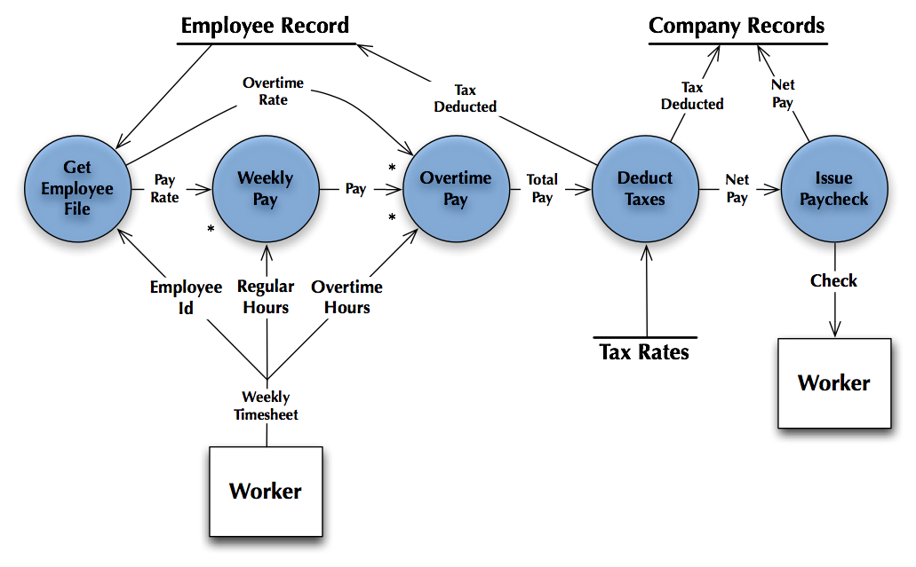
- Circles: Process or Function
- Rectangles: Data source and/or sink
- Arrows: Named data flows
- External Repositories shown as labeled straight lines
- Asterisk (*) indicates multiple required inputs to a process (process requires A AND B)
- Plus (+) indicates multiple inputs to a process such than only one is required (process requires A OR B)
DFD Example
Leveled DFDs
- It may be difficult to draw a DFD for a complex problem domain
- In that case, DFDs can be arranged hierarchically
- A child DFD will be associated with a process in its parent
- Need to make sure that the inputs flowing to the process in the parent are shown as inputs in the child
- Need to make sure that the outputs flowing from the process in the parent are produced as outputs by the child
Data Dictionary
- A data dictionary is simply a text file that provides more information about the data elements that appear in a system's DFD diagrams
- Can be as informal as natural language descriptions of each data element
- Sometimes special notations (such as regular expressions) are used to indicate patterns in the data
Structured Analysis
- Basic Idea
- A system is a series of functions that transform inputs to outputs
- If a function is too complex, decompose it into sub-functions
- Repeat until all sub-functions are simple enough to understand
- Basic Steps
- Construct a Context Diagram
- Construct DFD of existing system
- Construct DFD of proposed system, identify human-machine boundary
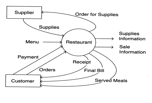
Context Diagram
- A high-level DFD that views the entire system as a function and specifies the system's context (primary inputs and outputs, data sources and data sinks)
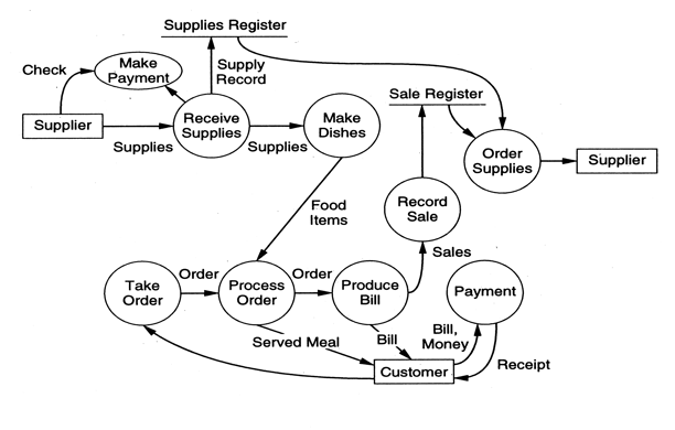
DFD of Existing System
- Current system is modeled as DFD to aid understanding of problem domain
- Start with context diagram and refine (using a leveled DFD)
- DFD is created via interaction with client, and is validated by walking them through the diagram
- Example Continued:
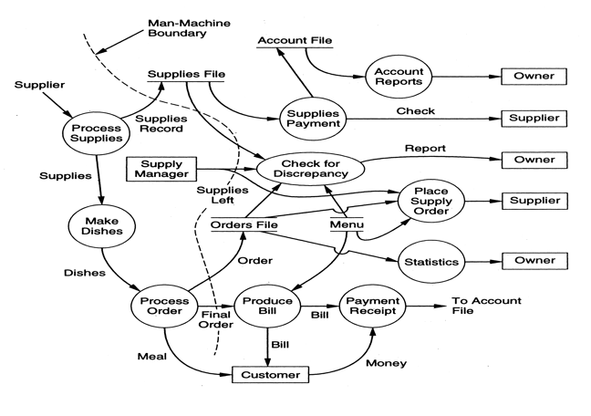
DFD of Proposed System
- Use existing system as a basis for modeling proposed system
- Now add new data sources, sinks, processes, and data flows
- At the beginning do not distinguish between automated and manual processes
- Once new structure is in place, validate with user to check understanding
- Then, identify automated processes, and show clearly how they interact with the manual processes
- Group automated processes, and use dotted line to indicate human-machine boundary
- Note: with the introduction of automated processes, some manual processes of the original system may disappear, new ones may be added
- Once a final DFD has been created, detailed requirements for each of the automated processes can be created
- Example continued:
Let's Try It Out!
- Construct a DFD for the following problem context:
- Patients in an intensive-care ward in a hospital are monitored by electronic devices attached to their bodies by sensors of various kinds. Through the sensors the devices measure the patients’ vital factors. A program is needed to read the factors, at a frequency specified for each patient, and store them in a repository. These factors are compared with safe ranges specified for each patient, and readings that exceed the safe ranges are to be reported by alarm messages displayed on the screen of the nurse’s station. An alarm message is also to be displayed if any device fails.
Coming Up Next
- Lecture 10: Software Requirements: Part 2
- Object-Oriented Modeling
- Prototyping
- Requirements Specification
- Lecture 11: Software Requirements: Part 3
- Use Cases
- Validation
- Metrics


